Tools needed:
·
Metric Allen wrench set
·
Philips and straight edge screwdrivers
·
Needle nose plyers
·
Wire cutters
·
Razor blade
Materials needed with the links for where I found
them
 |
| left to right, tai/brake light, instrument lights, tachometer/speedometer illumination and turn signals, each with original and LED replacement |
The only colored LED is the amber turn signal.
Note #2: I was able to get
everything from Gregory Bender at http://www.thisoldtractor.com/
and from Super Bright LED’s https://www.superbrightleds.com/
Mr Bender knows his motorcycles and their wires and is who I recommend first for any electrical work and parts on a Moto Guzzi.
The Super Bright people have a wide range of parts, most of which Mr. Bender does not carry.
Mr Bender knows his motorcycles and their wires and is who I recommend first for any electrical work and parts on a Moto Guzzi.
The Super Bright people have a wide range of parts, most of which Mr. Bender does not carry.
 |
| LED tail and turn signal |
The tail and brake lights are the easiest part. Just change the bulbs for the equivalent
LED’s. For the V11, I chose the natural
white LED’s because the back fixture includes a clear window to illuminate the
rear license plate. Otherwise somewhat better
brightness results come from matching the LED color to the red lens color. These are the kind that have a twist lock cylinder and two bottom
tips.
 |
| Original headlight bulb |
 |
| LED headlight kit |
There was room for both inside the V11 headlight assembly. Be careful to not place the converter or any wires in contact with the heat sink. The wires on the kit are long enough to also mount the converter out
The front running light is also in the front headlight assembly. It is easy to change. Note that the LED is slightly wider than the bulb we are replacing, but fits through the hole when aligned correctly. Gently wiggle, but DO NOT FORCE the light in. There is a small rubber ring at the base of the light that requires a small push, but that is after the rest of the light is all the way inserted.

The tachometer and speedometer lights also only require changing the bulbs. This is the same bulb and LED as the front running light, so gently find the path to get the LED in without forcing it in any way.
The six instrument lights on a v11 are high beam,
turn signal, neutral, oil, generator and low fuel. The turn signal is discussed below.
For all the others you must change the bulbs for LED’s with the bulb on. If the LED does not light up, take it out and reverse it. It should light. This is because LED’s are DIODES and electricity only flows one way through them.
For all the others you must change the bulbs for LED’s with the bulb on. If the LED does not light up, take it out and reverse it. It should light. This is because LED’s are DIODES and electricity only flows one way through them.
Do not change out the low fuel light. Even when off, the level sensor allows enough current to flow through it that the low fuel light will always come on, even with a full tank.
I used a straight edged screwdriver to wiggle the rubber
bulb holders out, and changed them one at a time so as not to get them
confused. A bit of spit and the same
screwdriver got them wiggled back into place.
 |
| empty turn indicator socket |
The turn signals are the tricky part.
One can easily do it only half way by only swapping out the
One can easily do it only half way by only swapping out the
rear bulbs for LED’s. That works, but the front bulbs and the
instrument panel bulb have to stay as they are.
To make everything LED requires an electronic flasher and to change the way the dash indicator bulb works using diodes. It is a little complicated, but not that complicated and all the materials are readily available.
To make everything LED requires an electronic flasher and to change the way the dash indicator bulb works using diodes. It is a little complicated, but not that complicated and all the materials are readily available.
1.
Pull out the turn signal instrument light holder
out and remove the bulb.
2.
Replace all 4 turn signal bulbs with the LED
equivalents. The V11 has amber lenses so
use amber LED’s.
 |
| Electronic and standard flashers' |
3 Replace the flasher unit with an electronic
flasher. Crimp on tabs and plug into the
same connections. Note that red is
positive. The V11 wiring harness had a
red striped positive female connection.
4 Test. The left and right should flash when the switch is in the right place. If they come on and do not flash or if nothing comes on, the electronic flasher might be reversed. (don’t forget to turn on the key)
5. Plug the incandescent indicator bulb back in. Normally, all 4 turn signals will flash, no matter which side the turn signal switch is clicked on. Unplug the incandescent bulb and it should work correctly. You have now verified that the indicator bulb is connected between the two circuits.
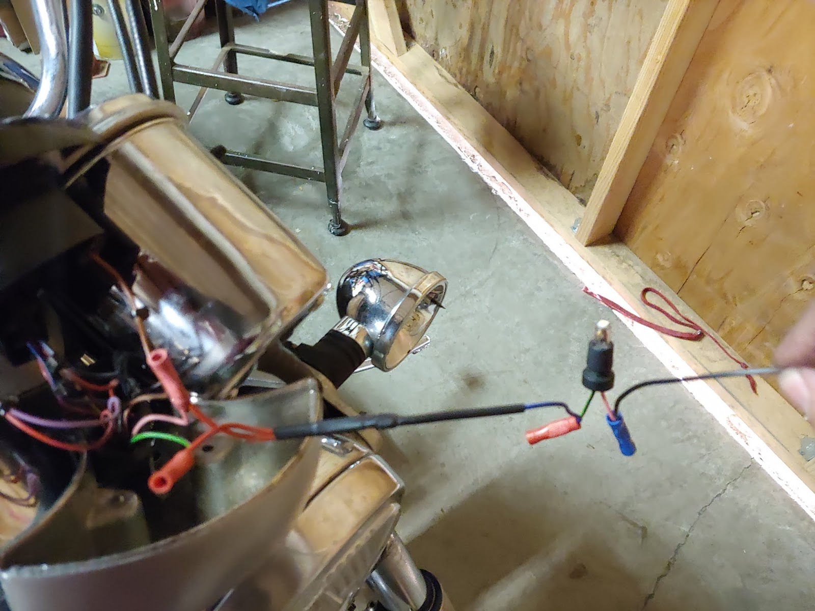 |
| connecting the diode kit to indicator bulb socket holding what is to become the ground wire |
6.
Cut both of the bulb’s mount leads off leaving enough extra
wire in both directions to strip and make connections.
7.
Temporarily attach the two positive sides of the
diodes to the two wires that used to go to the indicator bulb socket assembly.
8.
Temporarily attach the negative sides of the two
diodes to one side of the bulb socket holder.
9.
Now test the whole thing. Connect the
other side of the bulb assembly to ground ( I ran the ground wire down to the
frame), put the incandescent bulb back in again, and try both turn
signals. Now left and right should work
as normal and the indicator bulb should work for both. If the system does not work, go back and check the diode polarity and all
connections.
10. Replace the incandescent instrument bulb with the LED with the turn signals on and flashing. Same as all other instrument bulbs, the LED will only work one way and may need to be reversed.
11. Make all the connections permanent using some kind of crimp connectors.
12. Close the cover, check that ALL instrument
lights are working correctly before screwing it down.
Notes on the optical results.
Instrument lights are much easier to see during the day,
especially on clear days when the sunlight directly shines on the dash and one has sun glasses on under the helmet visor.
Part of the reason to go though the trouble for the turn signals is that one ends up with an indicator so bright that you will not miss it to remind the driver to turn the signal back off.
Part of the reason to go though the trouble for the turn signals is that one ends up with an indicator so bright that you will not miss it to remind the driver to turn the signal back off.
The speedometer and tachometer dials are much easier to see
at night, especially when driving in the city and competing with street light
glare.
Brake, tail and turn signals are much more visible to other
drivers day and night.
Headlight results are significant, especially with the high
beams at night hitting reflective signs.
Notes on the electrical circuits.
The LED’s use much less power in all cases and produce less
heat.
Such things as the headlight relay become less necessary,
and now are serving less amperage (flow) than they were designed for, but this
will not cause any functionally problems.
The biggest draw for power on the bike is still the starter
motor.
Second was the headlight, but after the LED change, is probably now the horn.
The turn signal description and advice is for an MG v11, but
is the same for most motorcycles that use a normal DOT flasher that clicks and have a
single bulb indicator light. (see schematic below)
Resistors are sold to make the turn signals work on the same
old flashers. Despite the name, what
they do is sit parallel to the LED lights and put MORE power through the wires
so that there is enough current for the flasher to work. When only using LED’s in the rear, the front
bulbs are playing that resistor role, and the flash is a little slower. There is really no advantage to using the
resistors and they produce heat. It is no more trouble to just change the
circuit.
This is a
schematic of the difference between the LED turn signals and the incandescent
ones that it is replacing:
